
To make this project you will need the following:
Parts
2. Adafruit Mini 8×8 LED Matrix w/I2C Backpack
3. Perfboard
4. Male to Female Pre Crimped Wire 6″
5. Crimp connector Housing 1×4
7. Box for Project (We 3d printed the box using www.makexyz.com Here are the 2 STL files you will need – 1. Lid 2. Box)
Miscellaneous Items
1. openweathermap.org key
2. WiFi username and password
Overview
This project uses the MKR1000 to connect to the internet and get time and weather. You will need WiFi. It displays time and weather on the 8×8 led display. We use icons to display general weather such as sunny, cloudy, rainy, night and use special icons for special events.
Special events include things like Valentines Day, birthdays, anniversaries etc. These are only displayed on the actual day. We have enclosed the project inside a 3d printed box with a removable lid.
To start off, collect your parts. Now, you could solder the connector wire directly to the MKR1000 but we added headers as we wanted to test it on a breadboard first.
Step One: Add Headers To MKR1000
So, the first thing is to solder headers on the MKR1000. We used a total of 12 headers in groups of 4. As we already had 4 piece headers.
The only pins you really need are 5V, GND, SCL, SDAT.
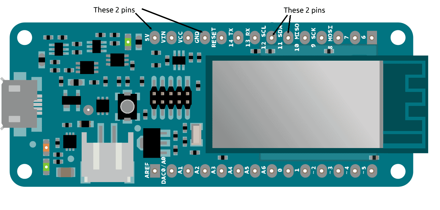
We put four headers on pins 5v, vin, vcc, gnd. We put the second 4 on scl, sda, miso, sck. The last 4 are on the other side on A5, A4, A3, A2.
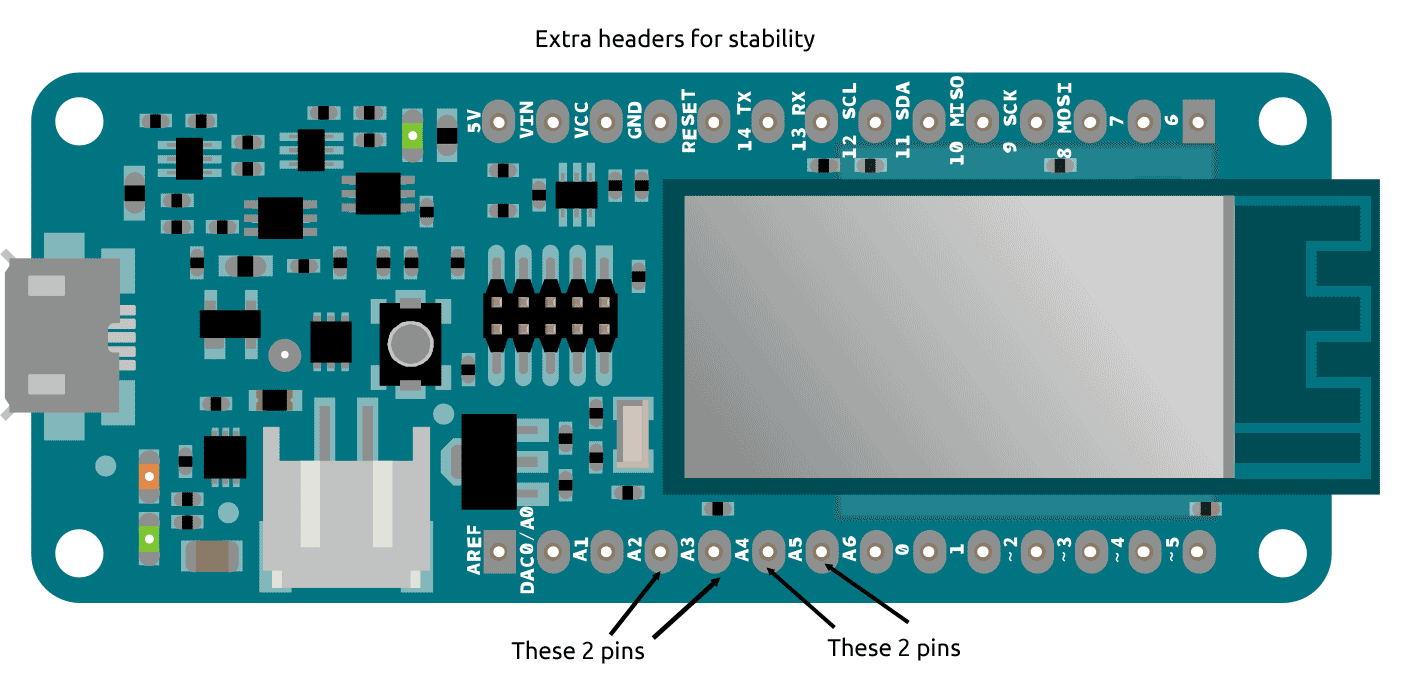
The 4 are on the other side on A5, A4, A3, A2. These are just for stability.
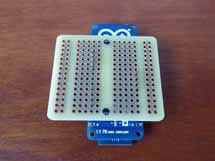
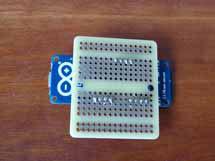
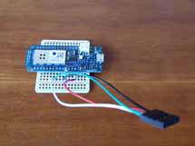
Solder the header pins on and the put the MKR1000 onto a breadboard.
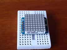
Step Two: Assemble 8×8 LED Backpack
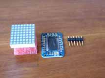
Add the 8×8 led display to the backpack. Be careful not to bend the pins. It may take a few minutes to get the pins in. If they are slightly out of alignment, try sticking them into a breadboard to straighten them out.
Also make sure you are putting them through the backside so they pin ends stick out of the side with the chip on it. Now solder the led pins on and then clip off the long ends when done soldering.
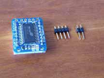
When this is done take some pliers and snap off 2 of the hears so you have a 4 piece. Go ahead and solder on the 4 header pins so that the long end faces away from the led display. It is easiest to do this buy putting the headers into a breadboard. Use the 2 extra header pins to pro up the side you are not soldering. When done soldering set this aside for later.
Step Three: Assemble The Connector
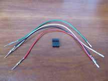
Get your 4 wires together and the crimp connector housing. We used black, red, green and white. We used 6″ wire and cut it a little shorter. You might be able to use 3″ wire as well.
Start out with the red wire first, then the black. Place the connector with holes facing up as in the photo above. Take the female end of the red wire and place the flatish side up and insert it into the the left most hole on the crimp connector.
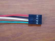
It should click into place and giving it a slight tug, it should not pull out. Great, now put the black wire next to the red wire , then the white and green.
You should end up with a connector like the photo below.
Cut off about 2 inches of wire and remove about 1/4″ of the plastic housing.
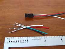
Great, the connector is done for the moment. Set it aside.
Step Four: Solder To Perfboard
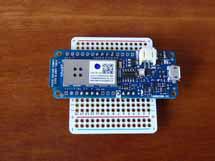
Lay the MKR1000 board upside down and put the Perfboard on it. Make sure not to cover up the 4 mounting holes on the MKR1000 in case you want to mount it inside your box. Solder 1 pin on each side and then put it into your holder or helping hands as it will be easier to solder.
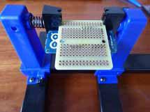
Fnish soldering on the header pins and it should look like this.
Now we need to solder on the connecting cable we made earlier.
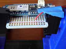
First solder the red wire to the perfboard in line with the +5 and the black wire to GND. We put the perfboard in our Circuit Board Holder and used some painters tape to hold the wire in place while soldering.
Here it is all done. Great, you have finished soldering. Turn your soldering iron off.
Step Five: Final Assembly

From inside the box insert the 8×8 led display so that the 4 header pins are on top and the leds face outside the box. The 8×8 led display should stay in place due to friction. Once you are all done and everything is working, you could add a few drops of glue to hold it in place.
Attach the connector making sure the red wire lines up with + on the right side and put the MKR1000 into your box.

Insert you micro usb cable through the hole in the back and insert it into the MKR100. Plug the other end into your computer.
Step Six: Software
Open up the Arduino IDE and make sure you have the following libraries installed.
Click on the links if you don’t have them. You can also update libraries from within the Arduino IDE. We already had Wire and SPI so did not need to install those.
#include <SPI.h>
#include <WiFi101.h>
#include <Wire.h>
#include <Adafruit_GFX.h>
#include “Adafruit_LEDBackpack.h”
#include <RTCZero.h>
Download the 2 files here. 1. WeatherBot 3000 2. Anim.h
The first file is the program and the second is the icons.
Open a new sketch and cut and paste in the program. Now click on down triangle on the top right hand side and add a new tab and call it anim.h. Open the icon file and cut and past it into the anim.h tab.
We are using openweathermap.org/to get the weather and parsing the data. To use openweathermap.org you will need sign up for a key. Once you have your key add it to this line of code after APPID= instead of all the x’s.
client.println(“GET /data/2.5/weather?id=4487042,us&units=imperial&APPID= xxxxxxxxxxxxxxxx HTTP/1.1”);
You will also need to set your location. Here I use my city ID as that is what they recommend. You can also use your zip code like this:
client.println(“GET /data/2.5/weather?zip=94040,us&units=imperial&APPID= xxxxxxxxxxxxxxxx HTTP/1.1”);
See this page on openweathermap.org for more info.
Two last things you will need to add are your WiFi settings. These 2 lines of code can be found near the top of the code before void setup().
Replace Network Name with the name of your WiFi and replace Password with your password.
char ssid[] = “Network Name”; // your network SSID (name)
char pass[] = “Password”; // your network password
That’s it! Now upload the code to the MKR1000 making sure you have the programmer set to ATMEL EDGB. I may take a couple of minutes before all the correct weather data is showing up.
The code here is given as is and certainly could use some improvement. We crudely set night time between 9 pm and 5 am to show the moon icon. This could be improved greatly.