
Sometimes it is easier to get your project working on a breadboard first. In this tutorial, we will explain how to take your project from the breadboard to a protoboard or perfboard.
Once you have your project working on the breadboard, leave it alone. This way you can refer to it when soldering the perfboard. This process is the same not matter how simple or complex your project is.
Now make sure you have all the same parts. For example, if your project on the breadboard has 2 capacitors, you need 2 more capacitors for a total of 4 capacitors.
In our example we will make a simple led circuit with a switch and a battery.
Here is the schematic. (added 11/5/16)
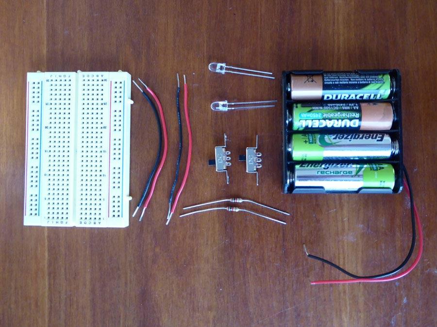
Here is our parts list and suggested links on where to get them. You may already have some these parts. If you already have resistors or leds just try them out on the bread board and see what works.
2 4 cell AA battery holder – AA Battery Holder With Lid & 6″ Wire Leads
8 AA batteries – Energizer L91BP-8 Ultimate Lithium AA Batteries (8-Pack)
2 5mm leds – 5mm Yellow LEDS Tayda Electronics
4 short wires – Black 22 AWG Wire
2 1k resistors Tayda1K OHM 1/4W 5% Carbon Film Resistor
2 slide switches Tayda Electronics
1 half breadboard –Experiment Breadboard
1 small perfboard
 +
+ 
To begin we will need to solder 2 wires to each of the switches.
Start by bending a small hook in one of the black wires and hooking onto the switch at either end and the soldering it.
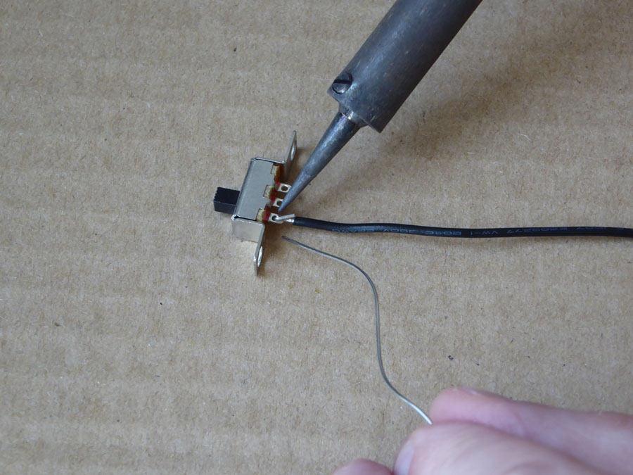
Then solder the the red wire in the middle. Make sure that neither wire nor the solder is touching each other. Now solder together the second switch the same way. The wire color for the switches does not really matter here. If all you have is one color of wire, that is fine.
Now let’s put the bread board together.
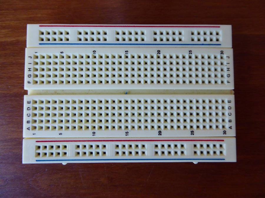
The red and blue areas are connected horizontally while the inside columns are connected vertically. Connect the red wire from the switch to the red line on the bread board and the black wire to a row in the middle of the board.
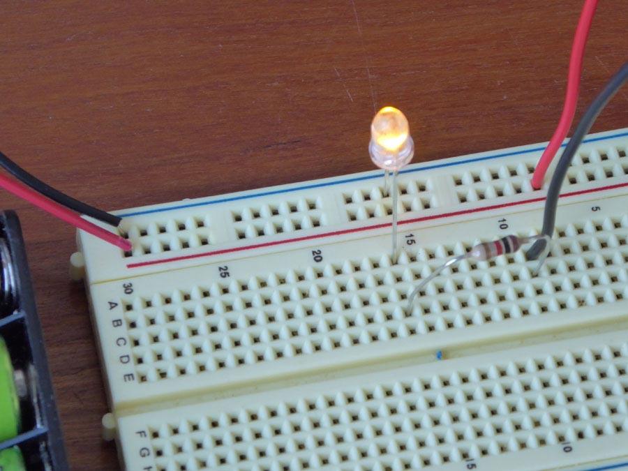
Now connect the led short lead onto the black line and the short side to the middle of the board.
Then add the 1k resistor connecting one end the the led column and the other end to the column that the black wire from the switch is in.
Now connect the black wire from the battery pack to the blue line on the breadboard and the red wire from the battery pack to the red line on the breadboard.
If your led does not light up then flip your switch. If it still does not work check your wiring.

Great, now that the breadboard version is working let’s solder the perfboard. Leave the breadboard alone for now and get all of the other parts.
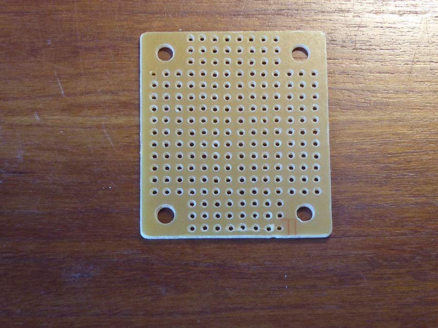
Unlike the breadboard, this perfboard has no hidden connections. Components are added by sticking the leads through the non copper side and then soldering them to the copper pads on the bottom, then bending them so they connect to other components. We need to make the same connections as we had on the breadboard.
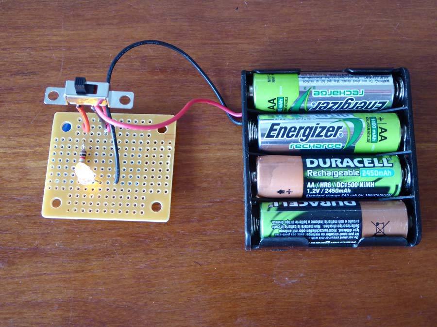
It is easiest to solder the perfboard if you put it in a vise, helping hands or use a circuit board holder like we did.
Start with your soldered switch and put the red wire through a top hole. We chose the second hole in and the second hole away from the corner. Really any hole that makes sense will do. Now solder the wire lead to the copper or bottom side of the perfboard. Don’t clip the leads just yet.
Now put the black wire through the top a couple of rows away from the red wire and solder it as well. Now add the resistor and put one lead in the same column as the red wire one or two holes away. Put the other lead through another hole in the perfboard.
Turn the perfboard over and bend the resistor lead so that it is connected to or touching the red switch lead.
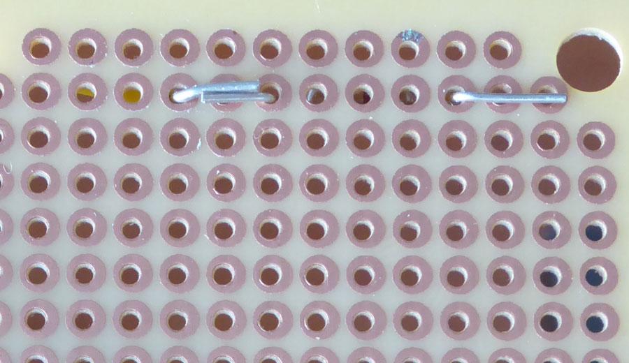
In the image above notice the two leads bent towards each other ready to be soldered.
Now solder the resistor led to the copper pad and at the same time solder the lead to the red wire lead. This may get a little messy, but that is ok as long as the 2 wires are soldered to the pads and together.
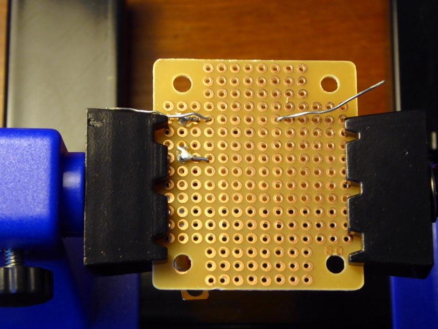
In the photo above, we have soldered the switch on and are about to solder the resistor.
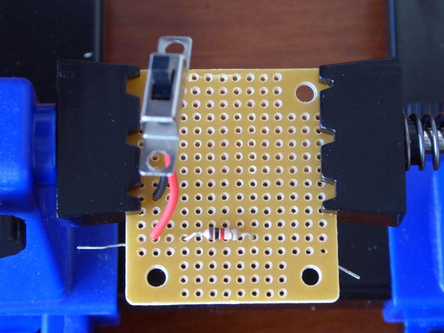
Now solder the other lead from the resistor to the copper pad. Now add the led by inserting the long lead through the top so that it is in the same column as the resistor and only one or two holes away. Bend the lead over on the bottom so it is touching the resistor lead. At the same time stick the shorter lead through another hole several columns away.
Solder the long led lead to the copper pad and the resistor lead. Solder the other led lead to the copper pad.
Now add the two leads from the battery pack. The red wire needs to connect to the black or second wire from the switch and the black wire from the battery pack needs to connect to the led.
Put the red wire in the same column as the second switch wire and bend it over to connect to the switch lead. Do the same for the black battery pack wire and the led lead.
Solder these in place and you are done.
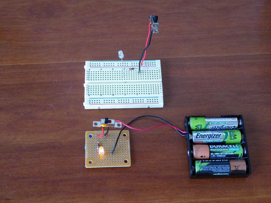
Here is the perfboard and the breadboard. As you can see I only had one battery pack but still have the rest of the breadboard circuit to refer to.
So that’s it. Follow a similar process on your next project and you can always refer to the breadboard version if something isn’t working right.